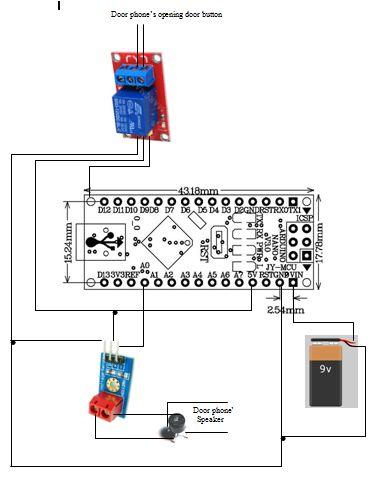
This project can be attached to a door phone so that when the doorbell button is pressed the door opens automatically.
Very useful for doctors offices with many patients like hematology lab. This hardware is for the building's main entrance (you can leave your office door open...:) )
While doorbell button is pressed you can pick an AC voltage in the speaker of the door phone. You can measure this trigger voltage using a DC voltage sensor.
Why a voltage sensor? Cause you isolate your arduino from voltages that could go as high as 12Vdc or 24Vdc. My voltage sensor also divides input voltage by ratio 5 to 1, so max input voltage is 25V.
In my case I have a trigger of 6.5VAC. This trigger voltage goes to a AC to DC diode bridge converter and then through the DC voltage sensor to the analog input A0.If analog input A0 returns a reads more than 4 Volts then digital I/0 pin 12 becomes high and triggers the 5V relay which is connected to button of door phone that opens the door.
Hardware:
Arduino Nano V3
Battery 9V
DC Voltage Sensor Module
1 Channel Relay Module Board 5V Module
Diode Bridge
Circuit:
Battery: Connect to Vin and GND of arduino(careful do not connect battery when you also have usb connected)
AC to DC diode bridge: AC pins goes to door phone's speaker pins, DC pins to DC voltage sensor.
Voltage sensor: Input + VCC goes to + pin of diode bridge, input GROUND goes to - pin of diode bridge, output S to pin A0 , output +Vcc to 5V pin, output ground to GND pin of arduino.
Channel relay: Trigger to Digital I/O Pin 12, +Vcc to 5V pin, Ground to GND pin of arduino.
Code:
// set pin numbers:
const int ledPin = 13; // the number of the LED pin
const int relayPin= 12; // the number of the Realy pin
const int AnalogInputPin = A0; // Sensor analog input pin
void setup()
{
pinMode(ledPin, OUTPUT); //set digital pin LED OUTPUT
pinMode(relayPin, OUTPUT); //set digital pin RELAY OUTPUT
Serial.begin(9600); //for checking input of voltage sensor when connected to PC
}//end void setup
void loop()
{
float sensorValue =0;
sensorValue = analogRead(AnalogInputPin); //Reads analog input A0 and returns value from 0 to 1023 (10 bit AD converter).
//float sensorRatio= ((5*5)/1023); //This one should have worked but didn't (5v max analog input * 5 times ratio of output to input of DC voltage sensor / 1023 max of A0 )
float sensorRatio= 22.646/1000; //!!!!Checking with serial monitor and using 2 batteries(1,2V & 9V) I measured their voltage with voltmeter I made this correction ratio. Before connection the diode bridge.
float voltIs = (sensorValue * sensorRatio)+ 0.6; // 0.6v is a diode's bridge average threshold voltage when there is no rectifier such as this case.
Serial.println(voltIs); // for checking voltage with serial monitor of arduino 1.0 software.
delay(200); // delay for 0,2 second to keep processor cool and noise free.
//When push button of door is pressed a 4,5V voltage is appearing in the door phone's speaker.
if ( voltIs > 3.95 && voltIs < 08.05) //Speaker voltage = 6,5 volts (yes I could have been more precise but had to make sure that door opens)
{ digitalWrite(ledPin, HIGH); //LED indication that relay circuit is closed
digitalWrite(relayPin, HIGH); //relay circuits is closed so door mechanism is on
delay (3500); //Delay door opening magnetic mechanism for 3,5 seconds so that patient passes through entrance.
digitalWrite(ledPin, LOW); // turn off Led
digitalWrite(relayPin, LOW); // relay back to NO
delay (20); // precaution delay
}
else
{
sensorValue=0; //precaution just in case there is anomaly not to open door.
voltIs = 0; //precaution just in case there is anomaly not to open door.
} //end if voltIs
}//end void loop
/*
Created @ 2012 by
Pagonidis Alexandros
www.BiomedicalTechnology.gr
*/
The final project in a box:
Well try not to use a metal box because you will need too much glue to isolate the circuits.


